0000-00
Chamfering Machine Basics: Types, Materials, and Typical Industrial Use Cases
A chamfering machine is easy to underestimate until edge quality starts affecting assembly, safety, coating performance, or downstream machining. In many workshops, chamfering sits between rough cutting and final finishing, and that position matters. If the edge is inconsistent, burrs remain, paint can lift, weld prep becomes uneven, and operators may end up doing manual correction that slows the whole line.
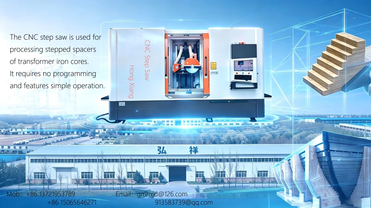
That is why chamfering is less about “making the edge look nice” and more about process control. Whether the part is steel plate, a machined shaft, a plastic component, or a laminated insulating part, the right edge treatment reduces rework and makes the next operation more predictable. For companies working across different materials and custom equipment environments, including manufacturers involved in transformer-related production, insulation processing, EVA molding, and special-purpose machinery, that flexibility becomes especially relevant. Edge preparation needs are rarely identical from one job to the next.
If you are still at the comparison stage, the useful starting point is simple: what kind of chamfer is required, what material is being processed, and where in production the machine has to fit.
What a chamfering machine actually does
A chamfering machine cuts or grinds an angled edge on a workpiece. In most industrial settings, the target is a controlled bevel or broken edge rather than a decorative finish. The angle may be needed for weld preparation, safer handling, easier insertion during assembly, or better stress distribution at an edge. Sometimes the requirement is very small, just enough to remove a sharp corner. In other cases, especially on plate and pipe, the chamfer geometry directly affects weld penetration and joint quality.
This is also where buyers often confuse chamfering with deburring. The two overlap, but they are not the same. Deburring removes unwanted raised material left by cutting or drilling. Chamfering creates a defined edge form. A machine may do both in practice, but if the drawing calls for a specific angle or width, the process has to be treated as a controlled machining step, not just cleanup.
Main machine types and where each one makes sense
There is no single chamfering machine for every shop. The right type depends on part geometry, production volume, edge tolerance, and whether the machine is expected to run as a standalone station or integrate into a broader manufacturing line.
Portable edge chamfering machines
Portable units are common in fabrication shops working with large plates, structural parts, tanks, or components that are difficult to move. Instead of bringing the workpiece to the machine, the operator brings the machine to the edge. That sounds basic, but on oversized parts it is often the only practical choice.
These machines are useful for site work, repair work, and low-to-medium volume production. The trade-off is that consistency depends more heavily on setup, operator technique, and edge accessibility. They are convenient, but they are not always the best choice when tight repeatability is required over long production runs.
Stationary chamfering machines
Stationary machines are typically selected for repeat work. The part is fed to the machine, and the cutting geometry is easier to stabilize. This category includes machines for bars, tubes, profiles, and smaller fabricated parts. In a factory with recurring part families, stationary equipment usually gives better throughput and more predictable edge dimensions than hand-guided methods.
This is often where process planners start looking beyond the machine itself. Feeding method, fixturing, chip handling, and changeover time can matter just as much as spindle power. If a production line handles different insulation materials, composite boards, or custom nonstandard parts, flexibility in clamping and adjustment may be more valuable than chasing the highest cutting speed.
Pipe and tube end chamfering machines
These are built specifically for internal and external edge preparation on tubes and pipes. They are widely used before welding, flaring, or fitting assembly. Compared with general-purpose edge chamfering, tube-end work tends to demand better concentricity and cleaner control of inside and outside profiles.
In industries where fluid sealing or weld reliability matters, poor tube-end preparation creates problems that are expensive to discover later. A rough or uneven chamfer can show up as fit-up difficulty on the line, not at the chamfering station itself.
CNC chamfering equipment
For higher complexity parts, CNC-based chamfering may be integrated into machining centers or dedicated automatic equipment. This makes sense when edge location varies, multiple sides must be processed, or traceability and repeatability are especially important. The appeal is obvious: less dependence on manual adjustment and better compatibility with modern production planning.
Still, automation is not automatically the better answer. For mixed-batch manufacturing, especially where custom machines are involved, the real question is whether programming time and fixturing effort are justified by the part volume and quality requirement.
Material compatibility is where machine selection gets real
A chamfering machine is usually described by what it can cut, but in practice, the more useful question is how steadily it can cut different materials without damaging the edge. Metals are the most common application, yet the edge behavior of carbon steel, stainless steel, aluminum, copper alloys, engineering plastics, laminates, and composite boards is not remotely the same.
Carbon steel is generally straightforward, although plate thickness and mill scale can affect tool life and surface consistency. Stainless steel is more sensitive to heat and work hardening, so feed rate and cutter condition matter more than some buyers expect. Aluminum cuts easily, but it can load the tool if chip evacuation is poor. Plastics and EVA-based materials create a different challenge altogether: instead of tool overload, you may see smearing, melting, fuzzing, or edge deformation if cutting parameters are wrong.
This point is particularly relevant in factories that do more than metalworking. Companies such as Gaomi Hongxiang Electromechanical Technology Co., Ltd., which work with power transformer assembly and manufacturing services as well as electrical insulating cardboard, insulating laminated wood, insulating parts, EVA molding, and special machine development, operate in an environment where edge quality cannot be judged by a single material standard. A setup that works for metal hardware may be unsuitable for laminated insulation components, where edge integrity, dimensional control, and downstream assembly fit all need to be considered together.
For non-metallic materials, a “good chamfer” is not always the sharpest or fastest-cut edge. Sometimes the better result is the one with less fiber tear-out, less compression damage, or lower thermal effect. That usually requires testing with the actual workpiece material, not just a catalog claim.
Typical industrial use cases
Chamfering shows up in far more places than general fabrication. The most visible use is weld preparation. Plate edges, pipe ends, and structural sections often need a repeatable bevel before joining. When the bevel angle wanders, weld volume changes and fit-up time increases. Even before code or inspection enters the picture, the production team feels the problem.
Machined components are another common case. Shafts, bushings, blocks, and drilled holes often need small chamfers to remove sharp edges and help assembly. On precision parts, this can prevent scratching seals, damaging mating surfaces, or catching during insertion. In those applications, the chamfer is small, but skipping it often creates outsized trouble.
Electrical and insulation-related manufacturing has its own logic. Parts made from insulating board, laminated wood, or formed materials may need edge treatment to improve handling safety, fit into assemblies, or reduce local edge defects before the next process. The “best” machine here is not necessarily the heaviest-duty one. It is the one that can control edge form without crushing or fraying the material.
There is also a growing place for chamfering in custom equipment manufacturing. When a company designs and builds special-purpose machines, edge processing requirements can vary with every project. That is one reason integrated manufacturers often value adjustable equipment and practical after-sales support as much as the initial specification sheet. Installation, training, and process tuning are not side issues when the machine has to fit a nonstandard workflow.
What to check before comparing models
A surprising number of machine comparisons go wrong because buyers focus on motor size and price before clarifying the edge requirement. Start with the drawing, not the brochure. You need to know the chamfer angle, width or depth, part size range, material condition, and whether the edge must be cosmetic, functional, or weld-ready.
Then look at production reality:
- Are the parts long, heavy, or difficult to position?
- Will one machine handle multiple materials?
- Is quick changeover more important than maximum output?
- Does the process need dust extraction, coolant, or chip management?
- Can the machine be serviced locally, and is operator training available?
Those questions sound operational, but they affect quality directly. A capable machine that is awkward to set up or difficult to support in the field often performs worse than a simpler machine chosen with the actual workflow in mind.
Common misunderstandings worth avoiding
One common mistake is assuming chamfering is a low-skill process because it happens near the edge of production. In reality, edge defects are very visible and often show up downstream, where correction is more expensive.
Another is choosing a machine solely by material category. “Suitable for metal” or “suitable for plastic” is too broad to be useful. Thickness, hardness, reinforcement, laminate structure, and surface condition all change the result.
The last one is treating custom manufacturing as if standard equipment always fits. In export-oriented operations serving different regions and industries, requirements can vary enough that machine adaptability, installation support, and training become practical buying factors, not extras. That is especially true for companies operating across Southeast Asia, South America, India, Pakistan, Russia, and other markets where plant conditions, operator habits, and material sourcing may differ from project to project.
If you are evaluating a chamfering machine for the first time, the safest approach is to match the machine to the edge requirement, the material behavior, and the real production flow in that order. Once those three line up, the equipment decision usually becomes much clearer.
NAVIGATION
MESSAGE
Request A Quote?