0000-00
Choosing a chamfering machine for beveling starts with the real workpiece
A chamfering machine for beveling is rarely selected by angle range alone.
In production, material behavior, edge condition, batch size, and downstream assembly all shape the right choice.
That is why the same beveling target can require different machines, cutters, or feed methods.
This matters even more where edge quality affects insulation fit, bonded surfaces, or safe handling.
In transformer-related manufacturing, laminated wood, insulating board, metal support parts, and formed components do not respond the same way.
A practical evaluation looks at what the edge must achieve after beveling, not just what the machine can claim on paper.
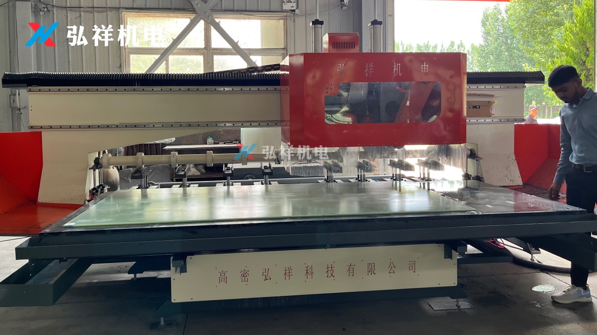
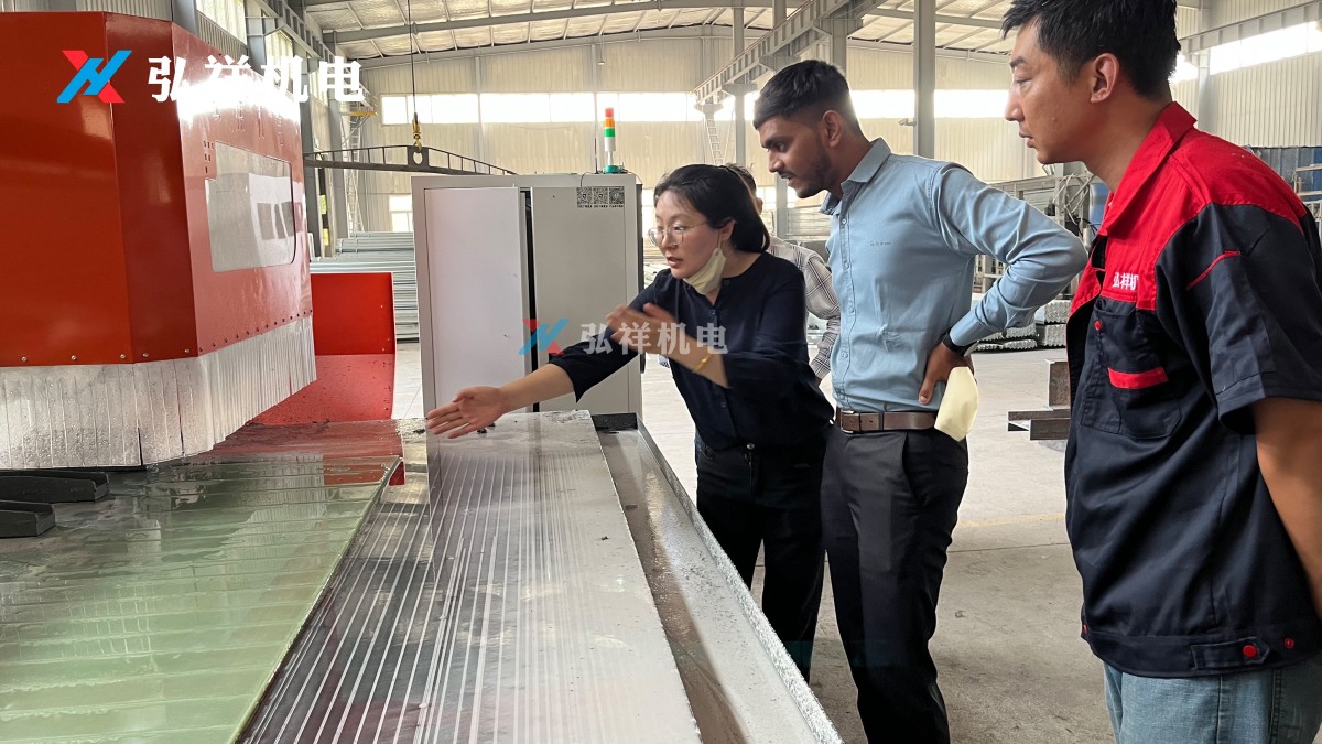
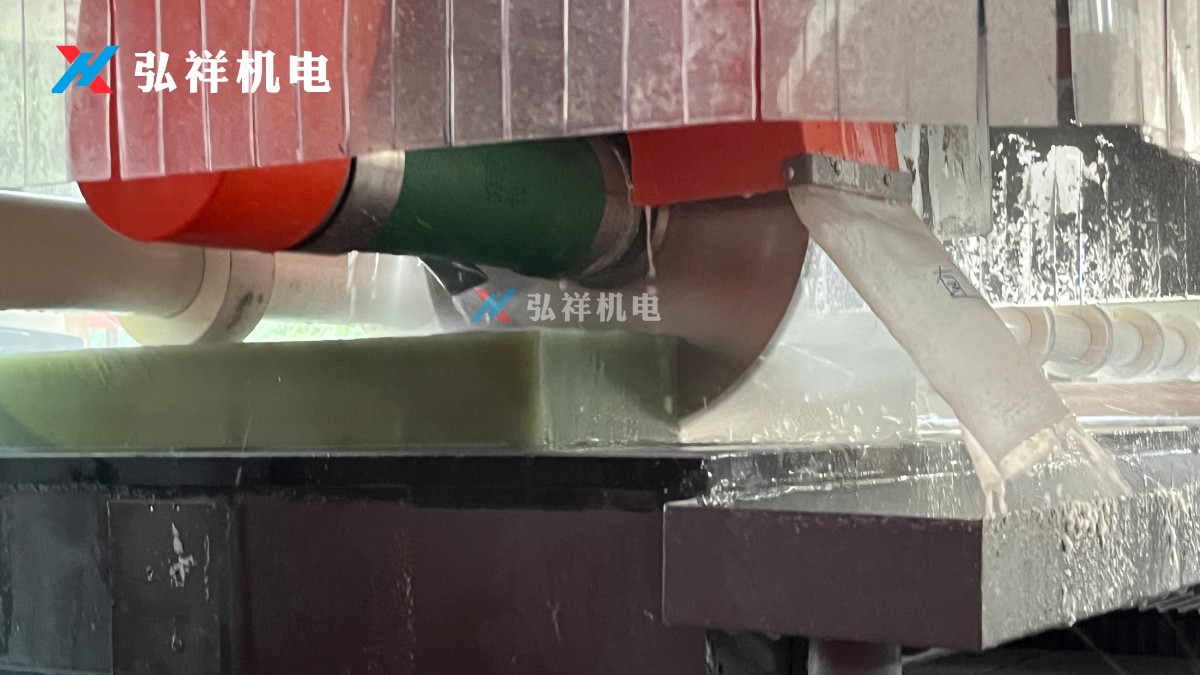
Why material and edge angle create very different beveling demands
The best chamfering machine for beveling depends on how the material fractures, compresses, melts, or burrs during cutting.
A mild steel edge may need stable chip removal.
An insulating laminated board may need cleaner support to avoid tearing.
EVA parts often need heat control and a lighter cutting action.
Angle also changes the load on the tool.
A small edge break, such as 1 mm at 45 degrees, is very different from a deep structural bevel.
Larger bevels increase contact time, cutting resistance, and the risk of chatter or inconsistent finish.
In actual use, the more useful question is not “Can it bevel?”
It is “Can it hold the required angle repeatedly on this material, at this speed, with this surface quality?”
Metal parts usually favor stable, repeatable chamfering at standard angles
For carbon steel, stainless steel, and aluminum parts, a chamfering machine for beveling is often used before welding, assembly, or deburring.
Here, the common target angles are 30 degrees, 37.5 degrees, and 45 degrees.
Those angles are preferred because they match common weld preparation and safe edge finishing practices.
What matters most in this scenario is feed stability.
If the machine vibrates, the bevel face becomes uneven and later fit-up suffers.
For stainless steel, heat buildup can harden the cut zone and shorten tool life.
For aluminum, chip adhesion is the usual problem.
A good setup therefore needs cutter geometry matched to the alloy, not only enough spindle power.
When production includes brackets, frames, and machine bases, standard-angle beveling is usually the easiest application for a chamfering machine for beveling.
Even so, edge straightness and thickness variation still need checking before deciding on an automatic feed version.
Insulating board and laminated wood call for cleaner edge support, not brute force
This is where application judgment becomes more specific.
Electrical insulating cardboard and insulating laminated wood are sensitive to fiber pullout, edge crushing, and local delamination.
A chamfering machine for beveling can work well here, but only when the cutting path supports the edge consistently.
In these materials, common bevel angles are often moderate.
The goal is usually safer assembly, better mating surfaces, or easier insertion into an insulated structure.
Very aggressive angles may look efficient at first, yet they increase breakout at the exit edge.
A sharper tool with controlled feed is normally more reliable than a faster, heavier pass.
For operations linked to transformer assembly or insulating part production, surface integrity often matters more than raw cycle time.
That is one reason integrated manufacturers such as Gaomi Hongxiang Electromechanical Technology often value machine adaptability, training, and after-sales support alongside cutting capacity.
EVA and softer formed materials need a different beveling strategy
Softer materials shift the decision again.
On EVA molded parts, the challenge is not heavy resistance.
It is keeping the bevel line clean without dragging, melting, or compressing the edge.
A chamfering machine for beveling in this environment should allow fine control over pressure and speed.
Larger bevel angles can deform the profile if the workpiece lacks support.
Smaller cosmetic bevels are usually easier to maintain than deep functional bevels.
This kind of work often benefits from trial samples across several feed settings.
The right result is judged by edge appearance, dimensional stability, and how the part performs in the next forming or bonding step.
Different materials and angles do not reward the same machine setup
A quick comparison helps clarify where a chamfering machine for beveling performs best.
What usually separates a good fit from a costly mismatch
The most common mistake is treating similar edge work as identical.
A chamfering machine for beveling that performs well on steel plates may be unsuitable for layered insulation parts.
Another mistake is choosing by maximum bevel size while ignoring minimum stable cut.
Many lines need small, repeatable bevels more often than large ones.
It is also easy to overlook the workholding condition.
Thin sheets, long strips, and soft profiles react differently under the same cutter.
In export-oriented production, another layer appears.
Different markets may expect different edge consistency, operator training levels, and maintenance access.
That makes serviceability and setup simplicity part of the application decision, not an afterthought.
Before final selection, match the machine to the process around it
A chamfering machine for beveling works best when the surrounding process is clear.
- Confirm the actual material family, hardness range, and thickness tolerance.
- List the bevel angles used most often, not only the most demanding one.
- Check whether the edge is for welding, fitting, bonding, insulation clearance, or safe handling.
- Review batch size and changeover frequency between different parts.
- Compare tool replacement time, dust or chip handling, and operator adjustment steps.
- Run sample cuts on real workpieces, especially for laminated or soft materials.
This approach prevents overbuying and reduces the risk of a machine that is powerful, yet poorly matched.
A practical way to decide which materials and angles are best
The best applications for a chamfering machine for beveling are the ones where angle accuracy, edge finish, and handling safety must stay consistent across repeated parts.
Metals usually favor standard bevel angles with stable removal.
Insulating board and laminated wood reward gentler, better-supported cutting.
EVA and similar materials need control more than force.
When the next step involves assembly precision or insulation reliability, bevel quality becomes part of product performance.
A useful next step is to sort current parts by material, target angle, bevel depth, and finish requirement.
Then compare those conditions against machine stability, tooling options, maintenance effort, and sample-cut results before locking in the final configuration.
NAVIGATION
MESSAGE
Request A Quote?